2 bit half adder truth table Half adder block circuit diagram ab carryout sum How to design half adder and full adder circuits?
Verilog code for Half Adder with Testbench
Adder subtraction circuits
Adder verilog diagram hierarchical adders shown coding boolean construct
[diagram] logic gate diagram full adderHalf adder Full adder circuit diagramAdder full half circuit carry ripple bit schematic diagram gate truth table delay doubt xor without electronics electrical representation shown.
Half adder and full adder using hierarchical designing in verilogHalf adder and full adder circuit Adder half circuit full subtractor diagram table block electrified get elec electronics study clubAdder in digital electronics, half adder and full adder in digital.

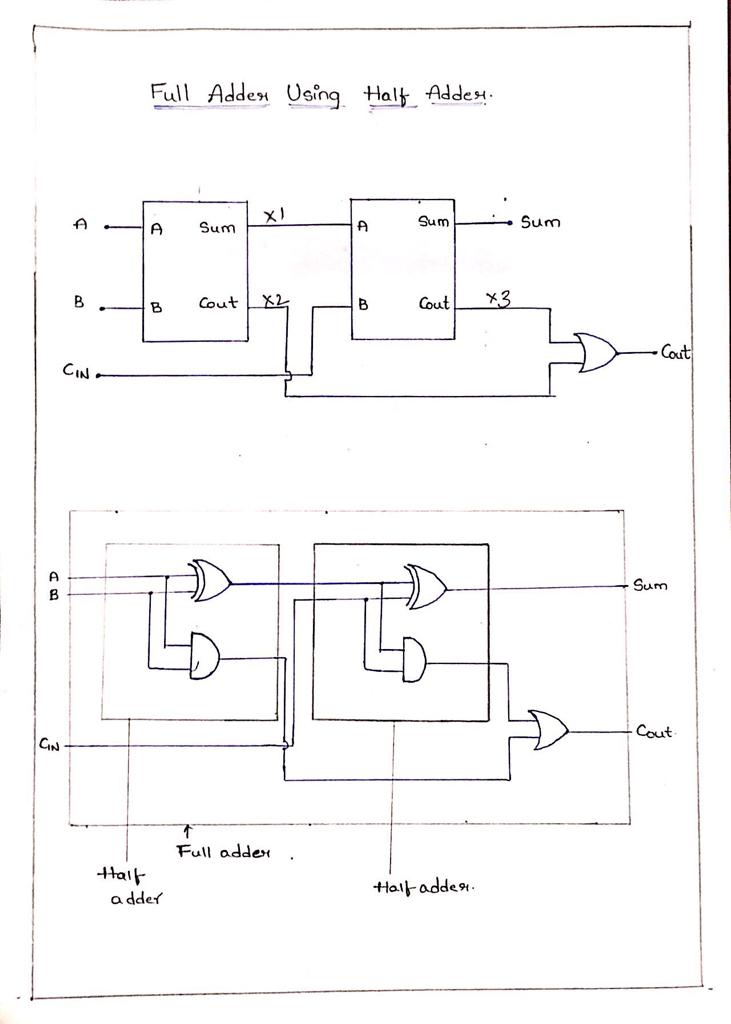
E-cad forum: full adder using half adder block diagram
Adder input outputs along13+ full adder block diagram Binary adder and subtraction circuits along with its various typesHalf adder full adders lab3 input block diagrams carry.
Half adder and full adder circuits with truth tableHalf adder circuit: theory, truth table & construction Half adder circuit diagram and truth tableHalf adder block diagram.

Full adder circuit diagram on breadboard
Half adder circuit diagram using icVerilog code for half adder with testbench Adder half subtractor binary full carry inputsApplication of half adder and half subtractor.
Adder half logic gate using gates nand only combinational sum implementation circuits expressions electronics tutorial carry output shows combinations including[diagram] bcd adder circuit diagram Full adder using half adder circuit diagramBinary adder and subtractor circuits: half and full adder, subtractor.

Half adder and full adder circuit with truth tables
Full adder circuit diagram using half adderAdder verilog hierarchical adders designing construct What is half adder and full adder circuit?Half adder circuit using logic gates.
How to design half adder and full adder circuits?Adder binary vidi theory gupta sourav Adder half full truth table bit binary xor schematic inputs circuit outputs show difference between verilog code diagram input outputLab3: half-adder.

Adder javatpoint
.
.